Pencarian

Rabu, 02 April 2014

Cisco CCNA Exploration 4.0 Chapter2 PT 2.6.1


Paket Tracer Exploration 2.6.1

Activity 2.6.1: 
Topology Orientation and Building a Small Network

Addressing Table

This lab does not include an addressing table.

Learning Objectives

  • Correctly identify cables for use in the network
  • Physically cable a peer-to-peer
  • Verify basic connectivity on each network

Introduction:

Many network problems can be fixed at the Physical layer of a network. For this reason, it is important to have a clear understanding of which cables to use for your network connections.
At the Physical layer (Layer 1) of the OSI model, end devices must be connected by media (cables). The type of media required depends on the type of device being connected. In the basic portion of this lab, straight–through or patch—cables will be used to connect workstations and switches.
In addition, two or more devices communicate using assigned addresses. The Network layer (Layer 3) requires a unique address (also known as a logical address or IP Addresses), which allows the data to reach the appropriate destination device.
Addressing for this lab will be applied to the workstations and will be used to enable communication between the devices.


Task 1: Create a Peer-to-Peer Network

Step 1. Select a Lab Partner

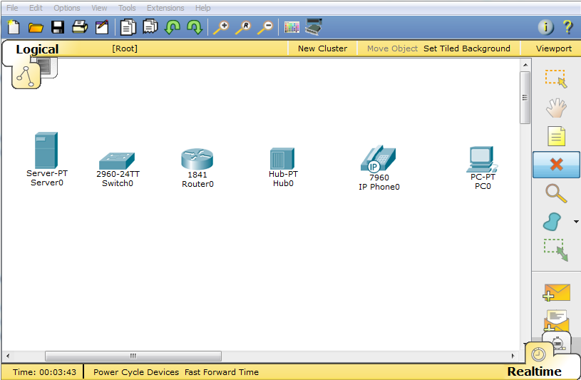
Step 2. Obtain equipment and resources for the lab.

Equipment needed:
  • 2 workstations
  • 1 Ethernet cable
MR3

 At the end of this task your completion rate should be 0%.

Task 2: Identify the Cables used in a Network

Before the devices can be cabled, you will need to identify the types of media you will be using. The cables used in this lab are crossover and straight-through.
Use a crossover cable to connect two workstations to each other through their NIC’s Ethernet port. This is an Ethernet cable. When you look at the plug you will notice that the orange and green wires are in opposite positions on each end of the cable.
Use a straight-through cable to connect the router’s Ethernet port to a switch port or a workstation to a switch port. This is also an Ethernet cable. When you look at the plug you will notice that both ends of the cable are exactly the same in each pin position.

Step 1. Cable the Peer-to-Peer Network.

Using the correct Ethernet cable, connect two workstations together. Connect one end of the cable to the NIC port on PC1 and the other end of the cable to PC2.Which cable did you use? stright-throught cable

MR3

At the end of this task your completion rate should be 33%.

Task 3: Configure addresses and test

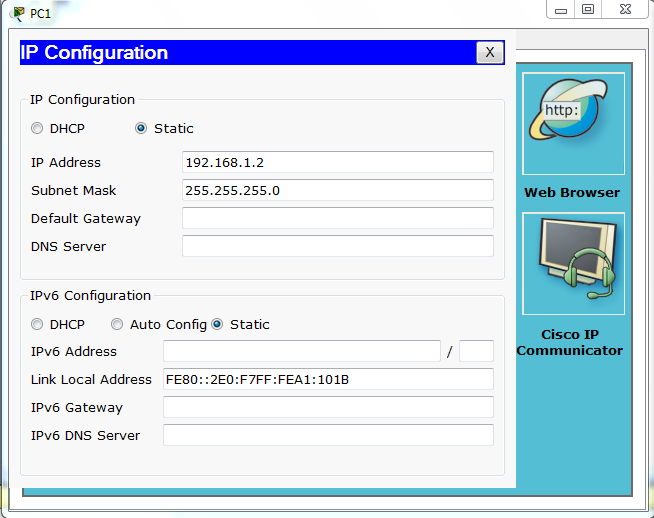
Step 1. Apply a Layer 3 address to the workstations.

To complete this task, you will need to follow the step-by-step instructions below.
  • Click the PC you want to assign an address to.
  • Click the Desktop tab
  • Click the IP Configuration tab
  •  In the IP address box, enter the IP address 192.168.1.2 for PC1. (Enter the IP address 192.168.1.3 for PC2.)
  •  Press the tab key and the Subnet mask is automatically entered. The subnet address should be 255.255.255.0. If this address is not automatically entered, enter this address manually
  • Close the IP configuration window by clicking on the X
MR3

MR3

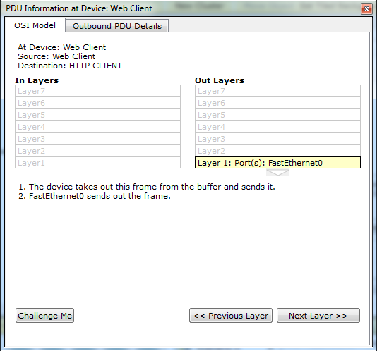
Step 2. Verify connectivity.

To test Connectivity follow the following instructions:
  • Click PC1
  • Click the Desktop tab
  • Click the Command Prompt tab
  • Type ping 192.168.1.3 then press enter
What is the output of the ping command? request timed out
If the ping command displays an error message or doesn’t receive a reply from the other workstation, troubleshoot as necessary. Possible areas to troubleshoot include:
  • Verifying the correct IP addresses on both workstations
  • Ensuring that the correct type of cable is used between the workstations
What is the output of the ping command if you unplug the network cable and ping the other workstation? request timed out

At the end of this task your completion rate should be 100%.


faldy-computer.blogspot.com


Rabu, 26 Maret 2014

Cisco CCNA Exploration 4.0 Chapter2 PT 2.4.8


Activity 2.4.8: Use of the TCP/IP Protocols and the OSI Model in Packet Tracer

Learning Objectives

  • Explore how PT uses the OSI Model and TCP/IP Protocols
  • Examine Packet Processing and Contents

Introduction:

In Packet Tracer simulation mode, detailed information about packets and how they are processed by networking devices may be viewed. Common TCP/IP Protocols are modeled in Packet Tracer, including DNS, HTTP, TFTP, DHCP, Telnet, TCP, UDP, ICMP, and IP. How these protocols are used by networking devices in creating and processing packets is displayed, in Packet Tracer, using a representation of the OSI Model. The term protocol data unit, or PDU, is a generic description of what are known as segments at the transport layer, packets at the network layer, and frames at the data link layer.

Task 1: Explore the PT interface

Step 1. Examine the Help Files and Tutorials

From the pull down menu, choose Help->Contents. A web page will open. From the left frame, choose Operating Modes->Simulation Mode. If not already familiar, read about simulation mode.
faldy-computer.blogspot.com 

Step 2. Switching from Realtime to Simulation Mode

In the far lower right of the PT interface is the toggle between Realtime and Simulation mode. PT always starts in Realtime mode, in which networking protocols operate with realistic timings. However, a powerful feature of Packet Tracer allows the user to "stop time" by switching to Simulation mode. In Simulation mode, packets are displayed as animated envelopes, time is event driven, and the user can step through networking events. Click the Simulation mode icon to switch from Realtime mode to Simulation mode.


Task 2: Examine Packet Contents and Processing 

Step 1. Creating a Packet and Accessing the PDU Information Window

Click the Web Client PC. Choose the Desktop tab. Open theWeb Browser. Enter the IP address of the Web Server into the browser, 192.168.1.254. 
 
faldy-computer.blogspot.com
 
Clicking Go will initiate a web server request. Minimize the Web Client configuration window. Since time in simulation is event driven, you must use the Capture/Forward button to display network events. Two packets appear in the event list, one of which has an eye next to it. An eye next to a packet means it is displayed as an envelope on the logical topology. Find the first packet in the Event List, and click the colored square in the Info column. 
 
faldy-computer.blogspot.com
  
Step 2. Investigating device algorithms in the OSI Modelview
When you click the Info square for a packet in the event list, or if you click a packet envelope displayed on the logical topology, thePDU Information window opens.

faldy-computer.blogspot.com
 The OSI model organizes this window. In the case of the first packet we are viewing, notice the HTTP request (at Layer 7) is then encapsulated, successively, at Layers 4, 3, 2, and 1. If you click through these layers, the algorithm used by the device (in this case, the PC) is displayed. View what is going on at each layer--this will be the subject of much of the rest of the course. 

Step 3. Inbound and Outbound PDUs

When opening the PDU Information window, the default is the OSI Model view. Now click the Outbound PDU Details tab.
faldy-computer.blogspot.com
 
Scroll down to the bottom of this window. 
 faldy-computer.blogspot.com
There you will see that HTTP (the web page request that started this series of events) is encapsulated as data in a TCP segment, which in turn is encapsulated in an IP packet, which in turn is encapsulated in an Ethernet frame, which in turn is transmitted as bits on the medium. 
If a device is the first device involved in a series of events, packets at that device will only have an Outbound PDU Details tab; if a device is the last device in a series of events, packets at that device will have only an Inbound PDU Details tab.
 
faldy-computer.blogspot.com
In general, you will see both Outbound and Inbound PDU details, which give details about how Packet Tracer is modeling that device. 

Step 4. Packet tracing: animations of packet flow

The first time through a packet animation, you are actually capturing the packets, as in a protocol sniffer. Hence, theCapture/Forward button means "Capture" one set of events at a time. Step through the web page request. Note that you are only displaying HTTP-related packets; but other protocols like TCP and ARP also have packets that are not being displayed. At any time in your packet capture, you can open the PDU Informationwindow. Run through the entire animation until the "No More Events" message is reached. Experiment with this packet tracing process -- running the animation again, examining packets, predicting what will happen next, and investigating your predictions.

Cisco CCNA Exploration 4.0 Chapter1 PT 1.7.1

Paket Tracer Exploration 1.7.1


1.7.1: Skills Integration Challenge-Introduction to Packet Tracer
Topology Diagram:
Nearly complete logical topology provided as starting point.
Device
Interface
IP Address
Subnet Mask
Default Gateway
R1-ISP
Fa0/0
192.168.254.253
255.255.255.0
N/A
S0/0/0
10.10.10.6
255.255.255.252
R2-Central
Fa0/0
172.16.255.254
255.255.0.0
N/A
S0/0/0
10.10.10.5
255.255.255.252
S1-Central
VLAN 1
172.16.254.1
255.255.0.0
172.16.255.254
PC 1A
NIC
172.16.1.1
255.255.0.0
172.16.255.254
PC 1B
NIC
172.16.1.2
255.255.0.0
172.16.255.254
Eagle Server
NIC
192.168.254.254
255.255.255.0
192.168.254.253

Learning Objectives:
  • Explore Packet Tracer Real-time mode
  • Explore the Logical Workspace
  • Explore Packet Tracer operation
  • Connect devices
  • Examine a device configuration
  • Review the standard lab setup
  • Overview of the devices

Cisco CCNA Exploration 4.0 Chapter2 PT 2.2.4

Paket Tracer Exploration 2.2.4

Activity 2.2.4: Network Representations

Addressing Table:

This Lab does not include an Addressing Table.

Learning Objectives:


  • Explore the PT interface
  • Locate the key components used to place device symbols in the logical workplace
  • Examine the devices that can be placed in the logical workplace and their symbols
  • Place and connect devices
  • Add device symbols to the logical workplace
  • Connecting devices in the logical workplace using auto connection

Introduction:

Packet Tracer is a network simulator that allows you create a simulated network, configure the devices in the network, test the network, and examine the traffic in the network. The first step in creating a simulated network in Packet Tracer is to place the devices in the logical workplace and connect them together. Packet Tracer uses the same symbols as are used throughout the curriculum. Match the icons in PT with the symbols in the symbol list.

Task 1: Explore the PT interface


Step 1. Logical Workspace

When Packet Tracer starts, it presents a logical view of the network in Realtime mode. The main part of the PT interface is the Logical Workplace. This is the large blank area where devices can be placed and connected.

  mr3

Step 2. Device Symbols


The lower left portion of the PT interface, below the yellow bar, is the portion of the interface that you use to select and place devices into the logical workplace. The first box in the lower left contains symbols that represent groups of devices. As you move the mouse pointer over these symbols, the name of the group appears in the text box in the center. When you click on one of these symbols, the specific devices in the group appear in the box to the right. As you point to the specific devices, a description of the device appears in the text box below the specific devices. Click on each of the groups and study the various devices that are available and their symbols.

  mr3


Task 2: Add devices to the logical workplace


Step 1. Selecting and Placing Devices

To add a device to the logical workplace click on the specific device symbol, point to where you want to place the device in the logical workplace (the pointer becomes a crosshair), and click. Locate and place the following devices in a horizontal row across the logical workplace, with about an inch between them, in order from left to right:

  • a server
  • a 2960 switch
  • an 1841 router
  • a hub
  • an IP phone
  • a PC

  mr3

 Step 2. Connect the devices using auto connect

Click on the connections group symbol. The specific connection symbols provide different cable types that can be used to connect devices. The first specific type, the gold lightning bolt, will automatically select the connection type based on the interfaces available on the devices. When you click on this symbol, the pointer resembles a cable connector. To connect two devices click the auto connection symbol, click the first device, and then click the second device. Starting with the server, connect each device to the device to its right using the auto connection symbol.


  mr3

 Step 3. Packet Tracer Scoring
Packet Tracer activities can be configured to score your work. To check your configuration, click the Check Results button below.

At the end of this task your completion rate should be 100%.


 mr3


Rabu, 05 Maret 2014

Menggunakan Google Earth ™ Untuk Lihat Dunia


Kegiatan 1.1.1 : Menggunakan Google Earth ™ Untuk Lihat Dunia
Tujuan Pembelajaran
Setelah menyelesaikan kegiatan ini, Anda akan dapat :
•Menjelaskan tujuan dari Google Earth
•Jelaskan berbagai versi Google Earth
•Jelaskan perangkat keras dan perangkat lunak persyaratan diperlukan untuk menggunakan  Google Earth ( edisi gratis ).
•Percobaan dengan Google Earth fitur seperti Bantuan | Tutorial .
•Percobaan dengan Google Earth untuk menjelajahi benua, negara , dan tempat-tempat menarik.

Latar belakang
Google Earth adalah aplikasi populer yang dijalankan pada desktop operasi sistem. Hal ini membutuhkan koneksi broadband ke Internet dan menampilkan bumi sebagai dimanipulasi 2D, atau gambar 3D. Saluran dunia itu berita populer, CNN, secara teratur menggunakan Google Earth untuk menekankan mana berita yang akan terjadi. Pada saat menulis kegiatan ini, ada tiga versions dari Google Earth. Versi yang paling cocok kebutuhan adalah Google Earth versi gratis. Versi Google Earth Plus termasuk dukungan GPS, spreadsheet importir, dan fitur pendukung lainnya. Google Earth versi Pro adalah untuk profesional dan penggunaan komersial. URL http://earth.google.com/product_comparison.html berisi deskripsi versi Google earth.
Gunakan link ini untuk menjawab pertanyaan-pertanyaan berikut :
1. Versi yang mendukung Tilt dan 3D rotasi ? Google Earth Enterprise, Google Earth Pro, dan Google Earth Free 
2. Google Earth versi yang mendukung resolusi tertinggi?  Google Earth Pro
Untuk menggunakan Google Earth, versi 4, minimum persyaratan perangkat keras komputer harus dipenuhi :
Spesifikasi minimal untuk Komputer:
Sistem operasi; Microsoft Windows 2000 atau Windows XP
Pentium 3 dengan 500 MHz
Memori Sistem ( RAM ) 128 MB
Hard Disk 400 MB ruang bebas
Kecepatan jaringan 128 kbps
Kartu grafis Kemampuan 3D dengan 16 MB VRAM layar
1024x768 pixels , 16 -bit High Color layar

Petunjuk
Kegiatan ini harus dilakukan pada komputer yang memiliki akses internet dan di mana Anda dapat menginstal software. Perkiraan waktu penyelesaian, tergantung pada kecepatan jaringan, adalah 30 menit .