Activity 2.2.4: Network Representations
Addressing Table:
This Lab does not include an Addressing Table.Learning Objectives:
- Explore the PT interface
- Locate the key components used to place device symbols in the logical workplace
- Examine the devices that can be placed in the logical workplace and their symbols
- Place and connect devices
- Add device symbols to the logical workplace
- Connecting devices in the logical workplace using auto connection
Introduction:
Packet Tracer is a network simulator that allows you create a simulated network, configure the devices in the network, test the network, and examine the traffic in the network. The first step in creating a simulated network in Packet Tracer is to place the devices in the logical workplace and connect them together. Packet Tracer uses the same symbols as are used throughout the curriculum. Match the icons in PT with the symbols in the symbol list.
Task 1: Explore the PT interface
Step 1. Logical Workspace
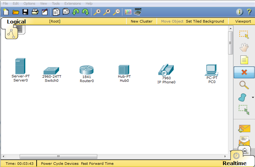
When Packet Tracer starts, it presents a logical view of the network in Realtime mode. The main part of the PT interface is the Logical Workplace. This is the large blank area where devices can be placed and connected.Step 2. Device Symbols
The lower left portion of the PT interface, below the yellow bar, is the portion of the interface that you use to select and place devices into the logical workplace. The first box in the lower left contains symbols that represent groups of devices. As you move the mouse pointer over these symbols, the name of the group appears in the text box in the center. When you click on one of these symbols, the specific devices in the group appear in the box to the right. As you point to the specific devices, a description of the device appears in the text box below the specific devices. Click on each of the groups and study the various devices that are available and their symbols.
Task 2: Add devices to the logical workplace
Step 1. Selecting and Placing Devices
To add a device to the logical workplace click on the specific device symbol, point to where you want to place the device in the logical workplace (the pointer becomes a crosshair), and click. Locate and place the following devices in a horizontal row across the logical workplace, with about an inch between them, in order from left to right:
- a server
- a 2960 switch
- an 1841 router
- a hub
- an IP phone
- a PC
Step 2. Connect the devices using auto connect
Click on the connections group symbol. The specific connection symbols provide different cable types that can be used to connect devices. The first specific type, the gold lightning bolt, will automatically select the connection type based on the interfaces available on the devices. When you click on this symbol, the pointer resembles a cable connector. To connect two devices click the auto connection symbol, click the first device, and then click the second device. Starting with the server, connect each device to the device to its right using the auto connection symbol.
Step 3. Packet Tracer Scoring
Packet Tracer activities can be configured to score your work. To check your configuration, click the Check Results button below.Step 3. Packet Tracer Scoring


Tidak ada komentar:
Posting Komentar