Paket Tracer Exploration 2.7.1
2.7.1: Skills Integration Challenge-Examining Packets
Topology Diagram:
A nearly complete standard lab topology is provided as starting point.| Device | Interface | IP Address | Subnet Mask | Default Gateway |
| R1-ISP | Fa0/0 | 192.168.254.253 | 255.255.255.0 | N/A |
| S0/0/0 | 10.10.10.6 | 255.255.255.252 | ||
| R2-Central | Fa0/0 | 172.16.255.254 | 255.255.0.0 | N/A |
| S0/0/0 | 10.10.10.5 | 255.255.255.252 | ||
| S1-Central | VLAN 1 | 172.16.254.1 | 255.255.0.0 | 172.16.255.254 |
| PC 1A | NIC | 172.16.1.1 | 255.255.0.0 | 172.16.255.254 |
| PC 1B | NIC | 172.16.1.2 | 255.255.0.0 | 172.16.255.254 |
| Eagle Server | NIC | 192.168.254.254 | 255.255.255.0 | 192.168.254.253 |
Learning Objectives:
- Complete the Topology
- Add Simple PDUs in Realtime Mode
- Analyze PDUs in Simulation Mode
- Experiment with the model of the standard lab setup
Background:
Throughout the course, you will be using a standard lab setup created from actual PCs, servers, routers, and switches to learn networking concepts. In this activity, you will continue learning how to build and analyze this standard lab topology. If you have not done so already, you are encouraged to examine the Help files available from the Help Pull-down menu at the top of the Packet Tracer GUI. Resources include a "My First PT Lab" to help you learn the basic operation of Packet Tracer, tutorials to guide you through various tasks, and information on the strengths and limitations of using Packet Tracer to model networks.This activity will provide an opportunity to explore the standard lab setup using Packet Tracer simulator. Packet Tracer has two file formats it can create: .pkt files (network simulation model files) and .pka files (activity files for practice). When you create your own networks in Packet Tracer, or modify existing files from your instructor or your peers, you will often use the .pkt file format. When you launched this activity from the curriculum, these instructions appeared. They are the result of the .pka, Packet Tracer activity file format. At the bottom of these instructions are two buttons: Check Results (which gives you feedback on how much of the activity you have completed) and Reset Activity (which starts the activity over, if you want to clear your work or gain more practice).
Task 1: Complete the Topology
Add a PC to the workspace.Configure it the following parameters: IP Address 172.16.1.2, Subnet Mask 255.255.0.0, Default Gateway 172.16.255.254, DNS Server 192.168.254.254, Display Name "1B" (do not include the quotation marks).
Connect PC 1B to the Fa0/2 port of the S1-Central Switch and check your work with the Check Results button to see that the topology is complete.
Task 2: Add Simple PDUs in Realtime Mode
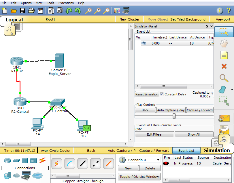
Wait until the switch link lights are green. Using the Add Simple PDU,send a test message between PC 1B and Eagle Server. Note that this packet will appear in the lower right as a user created PDU that can be manipulated for testing purposes. The first time you issue this one-shot ping message, it will show as Failed--this is because of the ARP process, which will be explained later. Double clicking the "Fire" button in the PDU List Window, send this single test ping a second time. This time it will be successful. Please do this prior to the next task.
Task 3: Analyze PDUs in Simulation Mode (Packet Tracing)
Switch to simulation mode. Use the Capture / Forward button to move the packet through the network.Click on the packet envelope, or on the colored square in the Info column of the Event List, to examine the packet at each step in its journey.


I got information about the zoom function, lenses, and recording function
BalasHapusavailable inside the CCTV. Get cheap <a
href="https://medium.com/@auctionszee/cctv-camera-installation-
service-in-delhi-noida-gurgoan-ghaziabad-d342665afd5e">CCTV Camera
Installation Service in Delhi</a>.
BalasHapushttps://www.codeninja.pk
A lot of people do not know how to do all this so they hire web development companies or experts. web development Company is offering its services for web development for new and old businesses.
It is such an informative blog and it is going to be very useful for laptop users. We can call Laptop repair expert in Nehru Place to get such issues solved if you are living in Delhi NCR.
BalasHapusWhile wiring your blog, you got all practical information inside the contents.To get the computer repaired call at Laptop parts dealer in Nehru place from any part of Delhi NCR.
BalasHapus